
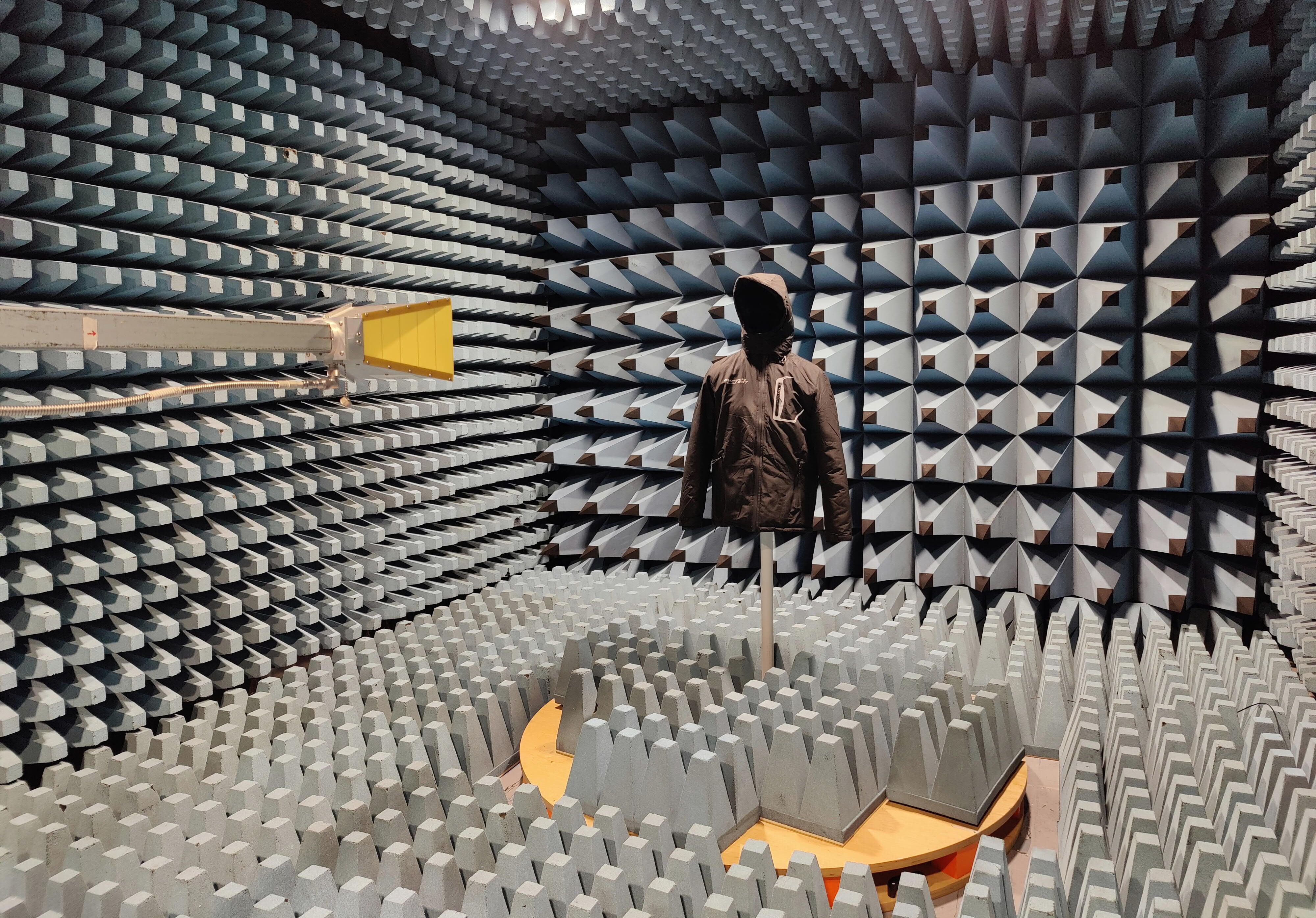
This service is tailored for manufacturers of technical textiles, protective clothing, and military EMI shielding clothing, as well as defense contractors, system integrators, NATO suppliers, and R&D departments. Testable materials and items include metallized fabrics, conductive meshes, multilayer laminates, RF suits, military shielding uniforms, jackets, hoods, balaclavas, gloves, and other wearable components intended for operation in complex electromagnetic environments.
Methodology note: IEEE 299 specifies the measurement of shielding effectiveness for electromagnetic enclosures. For technical fabrics and finished garments, EMCTEST applies a tailored and documented methodology based on the principles of IEEE 299. Frequency ranges, test configurations, and acceptance criteria are defined within the test plan according to the specific product and its intended operational application.
Why the Complete Garment Must Be Measured
Raw material shielding performance is merely the baseline. In the finished wearable product, zippers, fasteners, seams, face and hand apertures, jacket-to-trouser overlaps, and interfaces with gloves or footwear can introduce electrical discontinuities and RF coupling paths.
For this reason, we implement two distinct levels of characterization:
| Product Family | Testable Sample Examples | Critical Evaluation Aspects |
|---|---|---|
| Military Shielding Clothing | Tactical EMI/RFI uniforms, military shielding garments, Faraday suits, anti-EMP suits, shielding jackets and trousers | Electrical continuity across assemblies, closures, overlaps, hood, gloves, footwear, and operational fit configuration |
| RF Suits & Operator PPE | RF protective suits, antenna and transmitter maintenance garments, radar operator suits, microwave protective clothing | Attenuation across operational frequency bands, anatomical coverage, apertures, ergonomics, and orientation relative to the RF source |
| Conductive Clothing for Live-Line Work | Conductive workwear suits, jackets, trousers, hoods, gloves, socks, and footwear designed to establish an equipotential surface | Overall electrical continuity, component-to-component bonding, and shielding performance of the donned system |
| Conductive Fabrics & Laminates | Silver-plated fabrics, stainless steel fiber blends, copper-nickel textiles, metallized ripstop, conductive non-wovens, meshes, and multilayer structures | Intrinsic attenuation, anisotropy, material uniformity, weave and knit effects, and comparative analysis of layer stack-ups |
| Shielding Accessories & Components | Hoods, conductive balaclavas, RF gloves, vests, aprons, shielding base layers, and protective inserts | Localized RF attenuation, perimeter edges, seam joints, bonding with adjacent PPE, and potential RF leakage points |
| Mobile Shelters & Field Systems | Faraday tents, SCIF tents, military shielded shelters, portable RF cabins, and deployable shielded enclosures | Seams, floor interfaces, modular panels, entry doors, optical windows, ventilation honeycomb panels, cable penetration panels, and inter-module bonding |
| Shielding Curtains & Covers | EMI curtains, conductive drapes, canopies, RF blankets, removable textile covers, and flexible shielding wraps | Overlap effectiveness, mechanical fastening systems, perimeter electrical continuity, and installed shielding performance |
| Textile Shielding Enclosures & Pouches | Faraday bags, RF shielding pouches, shielding bags and backpacks, enclosures for tactical radios, mobile devices, and forensic hardware | Closure mechanisms, seam folding, seam integrity, degradation under repeated access cycles, and enclosure attenuation across target bands |
This comparative framework also enables side-by-side benchmarking of design prototypes or specific sub-components, such as hoods, gloves, panels, closures, and seams. The geometric setup is kept strictly identical to ensure technical validity and measurement repeatability.
Shielding Effectiveness Measurement
Shielding Effectiveness (SE) quantifies the signal reduction introduced by the sample under test, expressed in decibels. In the power domain, it is calculated as:
SE [dB] = Preference [dBm] − Pwith sample [dBm]
A higher SE value denotes greater electromagnetic attenuation. However, data is only meaningful when linked to specific frequency points, field polarization, incident wave angle, receiver positioning, and available measurement dynamic range. A single average figure is technically inadequate to characterize the behavior of a shielding garment.
Testing of Conductive Fabrics
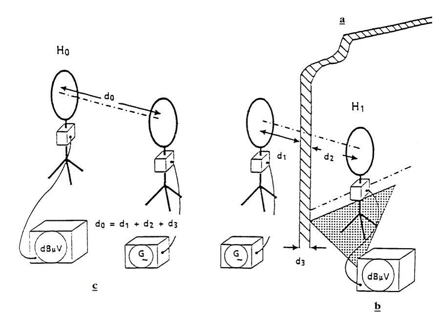
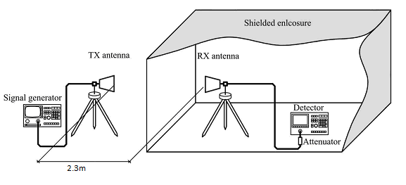
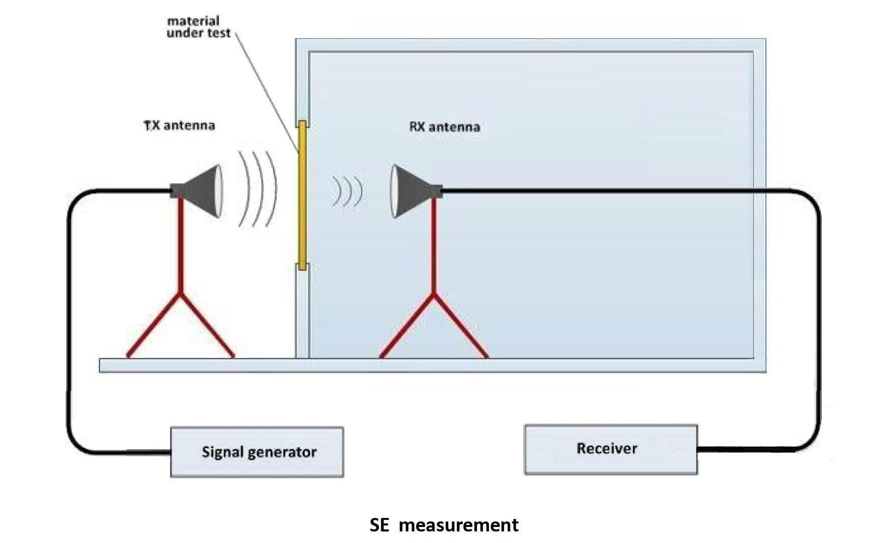
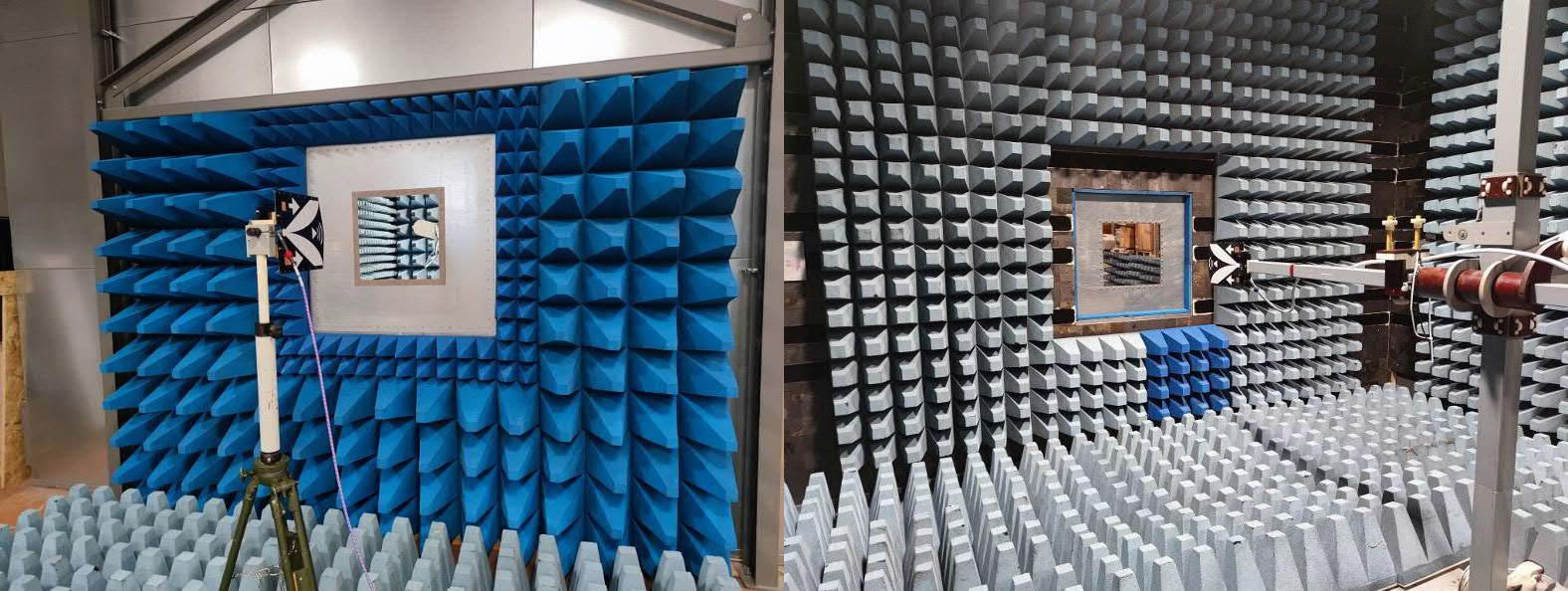
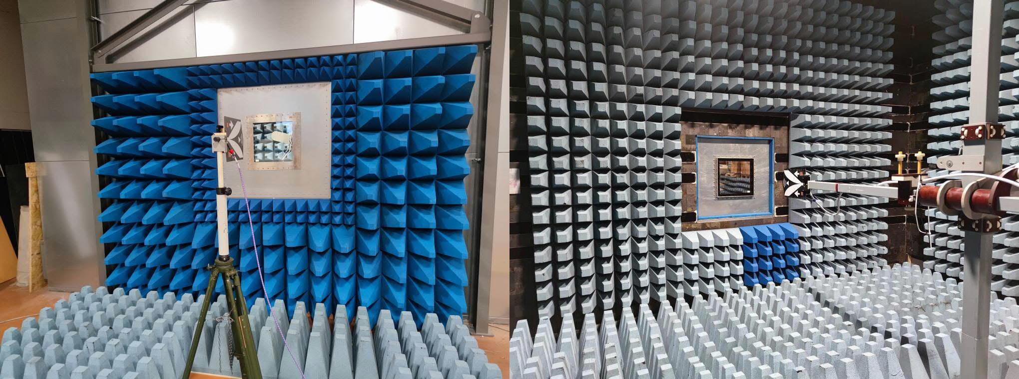
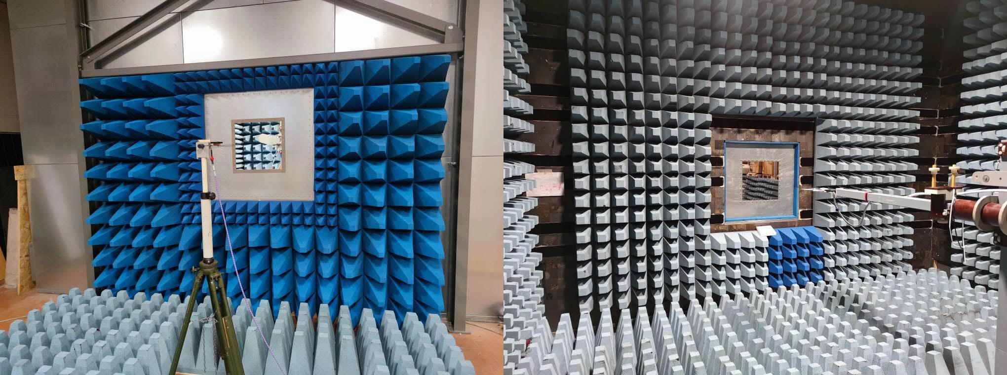
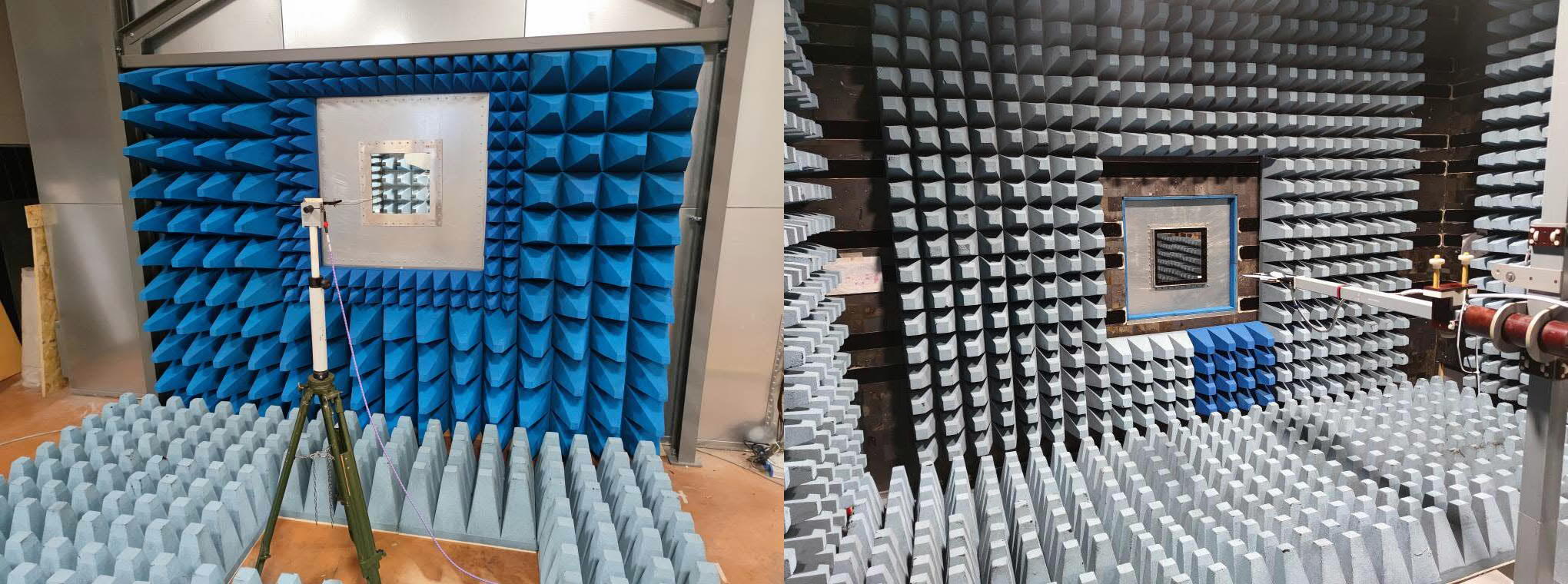
Planar material samples are mounted across a test aperture built into the wall of a shielded anechoic chamber. A transmitting antenna and a receiving antenna are positioned on opposite sides of the partition, aligned along the same boresight axis and configured with matching polarizations.
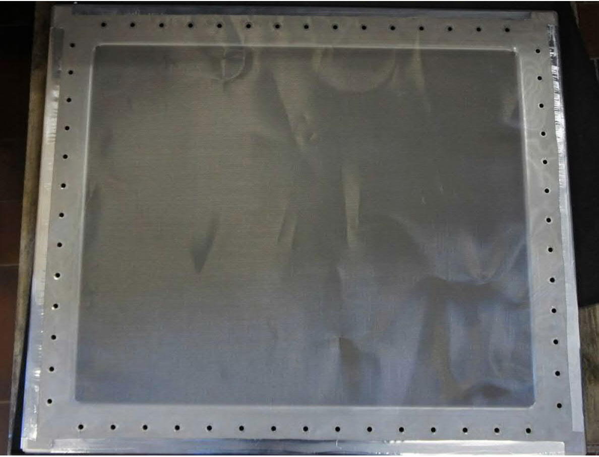
A baseline reference power level is acquired through the open aperture, followed by measurement of the transmitted signal level with the sample installed, keeping antennas, separations, heights, cabling, and instrumentation settings strictly unchanged. Measurements are performed in both vertical and horizontal polarizations to characterize any material anisotropy related to yarn structure, warp, or weft orientation.
Under the standardized test configuration documented by EMCTEST, the total antenna separation distance is 230 cm (115 cm on each side of the wall aperture). The optical center axis aligns with the sample center at 154 cm above the floor, with geometric alignment verified via laser leveling.
Testing of Garments and Military Uniforms
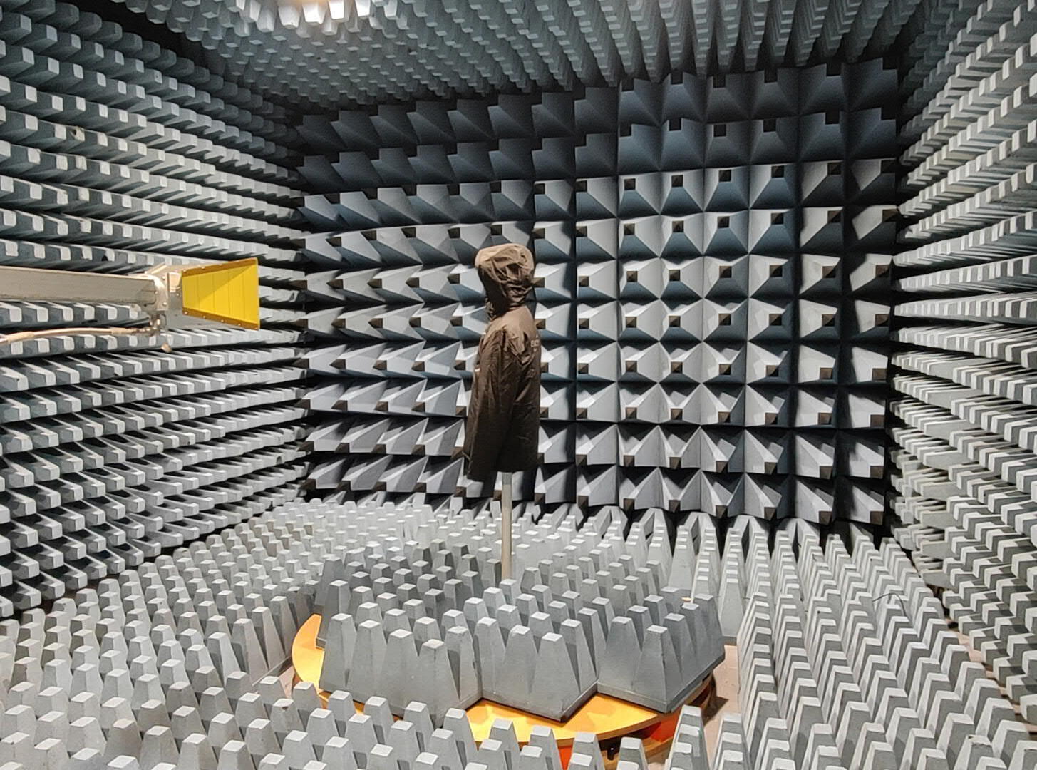
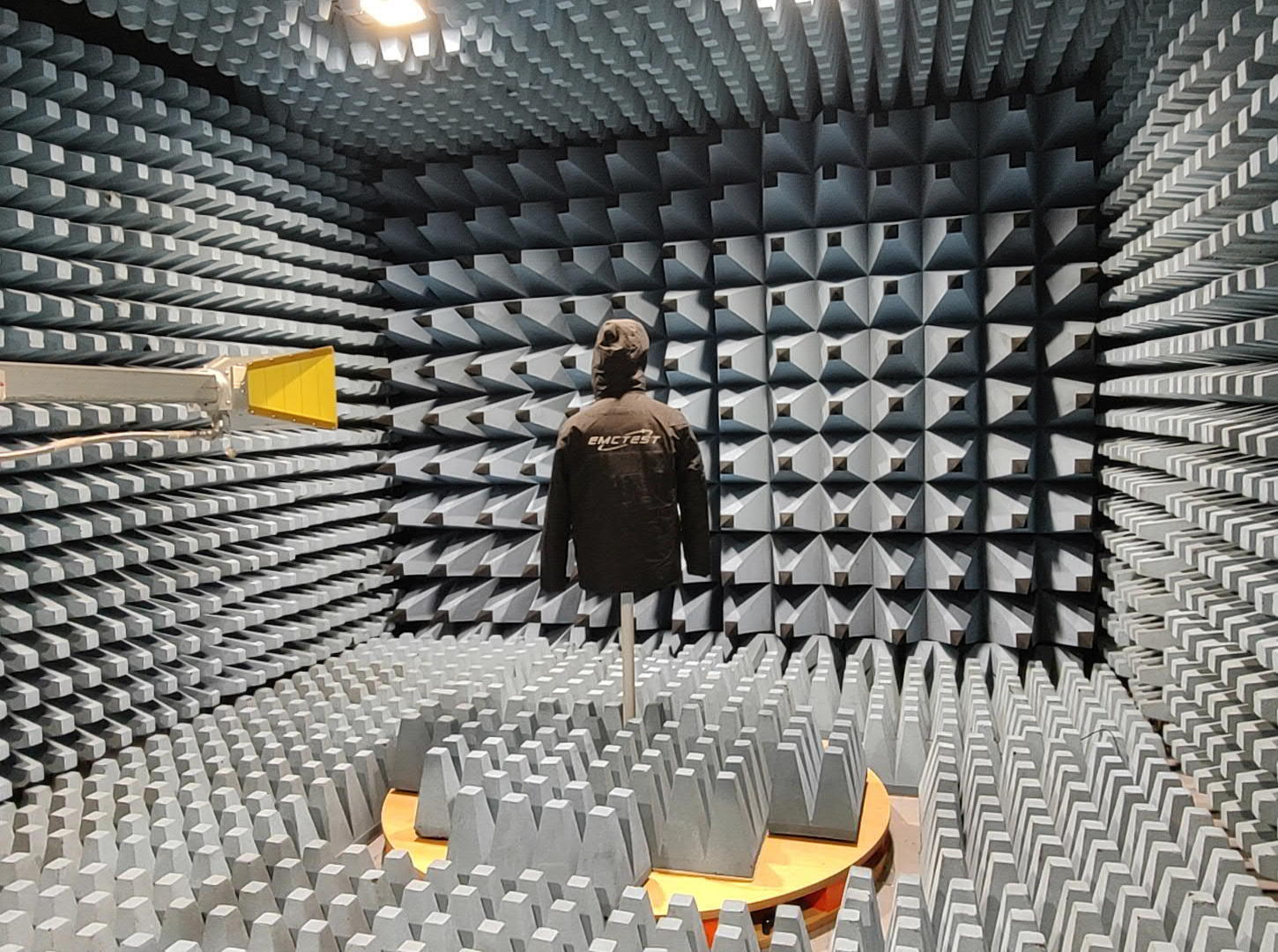
To evaluate an RF shielding suit or a complete uniform ensemble, the garment is fitted onto a full-scale polystyrene mannequin mounted on a dielectric pedestal at the center of a turntable. A directional antenna illuminates the setup with a CW signal, while a compact omnidirectional antenna inside the mannequin measures the received field intensity.
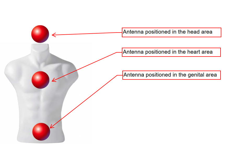
The baseline reference is measured using the unclad mannequin; testing is then repeated with the protective garment donned, maintaining the internal antenna position and orientation constant. The mannequin is evaluated across four azimuth orientations (0°, 90°, 180°, and 270°) in both vertical and horizontal polarizations. The internal RX antenna is systematically positioned in three representative anatomical regions: head, chest, and pelvic area.
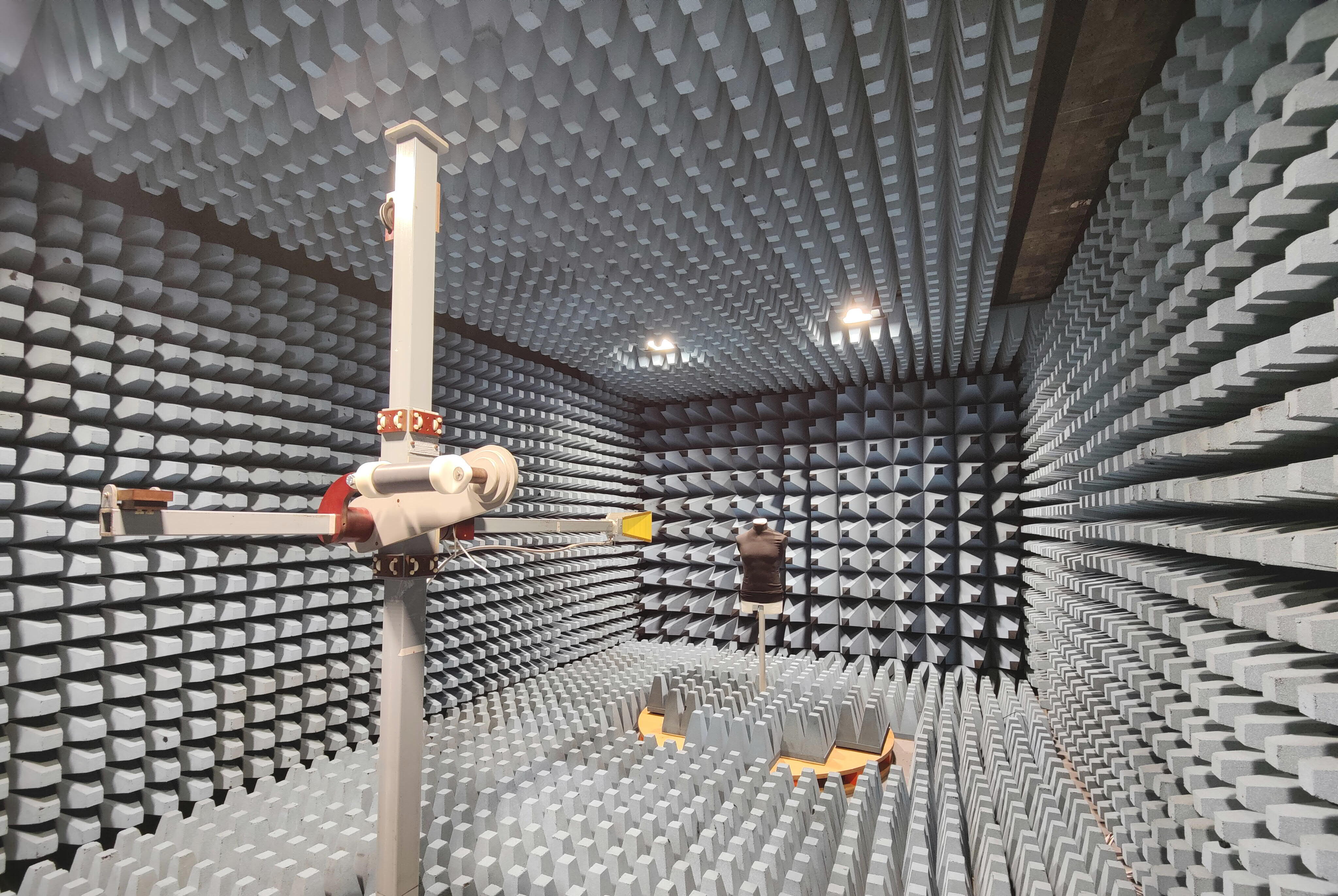
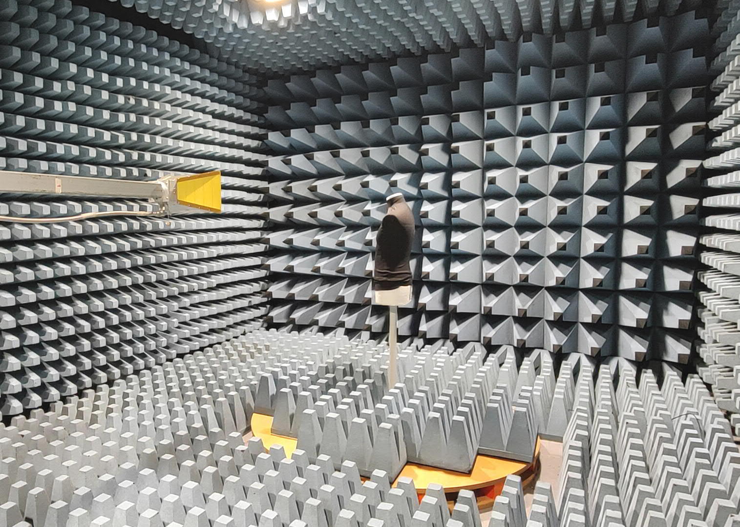
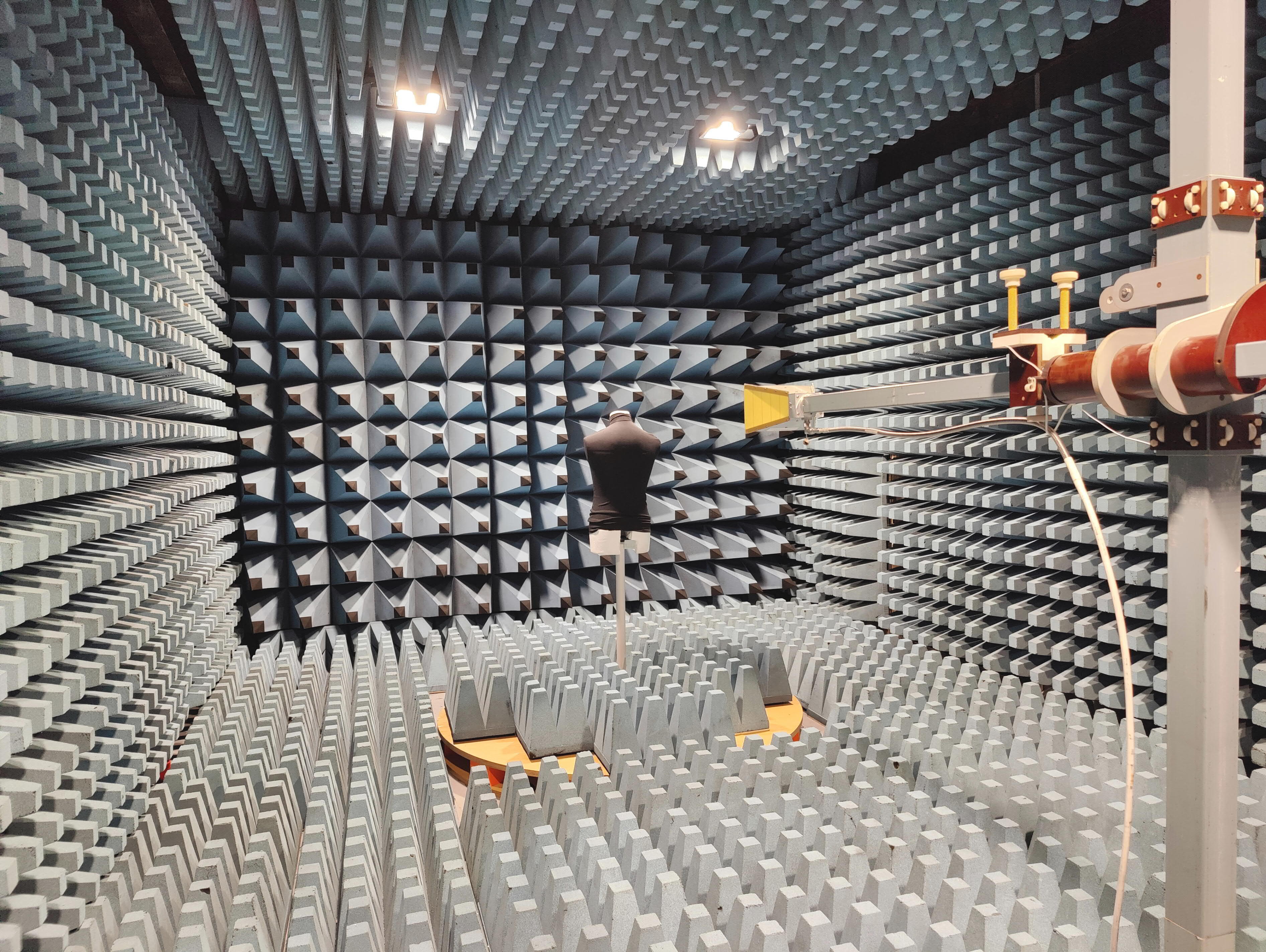
24 distinct measurement conditions: 4 azimuth orientations × 2 field polarizations × 3 anatomical zones. The resulting curves characterize full 360-degree shielding protection across the body, revealing seams, closures, and structural leakage that coupon-level fabric testing cannot detect.
Data Integrity and Test Report Deliverables
The RF test instrumentation chain must operate strictly within its linear dynamic range. Available measurement dynamic range is verified via a calibrated step attenuator and must exceed the target SE by at least 6 dB. Baseline reference traces are re-acquired whenever geometric or instrumentation parameters change to safeguard measurement repeatability.
A comprehensive test report includes:
- Shielding attenuation curves as a function of frequency;
- Minimum and average SE values across contracted frequency bands;
- Comparative analysis across polarizations, incident angles, and body zones;
- High-resolution test setup photography, instrument registry, and sample state records;
- Direct performance benchmarking between materials, prototypes, or design revisions.
Optional test matrices can evaluate samples before and after industrial laundering, mechanical abrasion, flex-folding, or accelerated environmental aging. This confirms not only the initial performance of the conductive fabric, but also the long-term integrity of the RF shield throughout its operational lifecycle.
Target Applications and Testable Products
This test methodology applies to EMI shielding garments, Faraday suits, RF protective clothing, personnel protective gear for radar and high-power broadcast environments, wearable shielding accessories, and specialized textile structures used across defense, aerospace, telecommunications, electronic warfare (EW), EMC test facilities, homeland security, and research laboratories.
Electromagnetic shielding characterization is complementary to, and does not replace, mandatory qualification standards for ballistic, CBRN, electrostatic discharge (ESD), or electric arc flash protection. Where products must comply with defense procurement standards or client-specific technical requirements, applicable limits are integrated directly into the test matrix.
Why Choose EMCTEST Technologies
EMCTEST pairs a dedicated shielded anechoic chamber with specialized engineering expertise in shielding effectiveness characterization and customized test protocols. Beyond delivering raw attenuation values, we analyze full-assembly behavior, document test setups thoroughly, and deliver engineering-grade data to support material selection, prototype R&D, and technical qualification.
Defining a test program requires only preliminary product details: garment style and sizing, material stack-up, target frequency ranges, expected SE, operational posture, sample quantities, and applicable pass/fail criteria. Our technical team can then formulate a targeted test plan that avoids superfluous measurements while capturing critical operational performance.
Request a Technical Consultation
Looking to characterize a conductive textile, an RF protective suit, or a military tactical uniform? Submit your product specifications: EMCTEST Technologies will configure the test setup and testing parameters needed to deliver clear, repeatable, and fully comparable shielding effectiveness data.